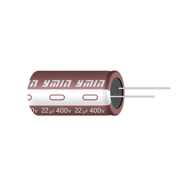
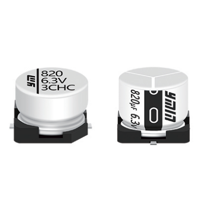
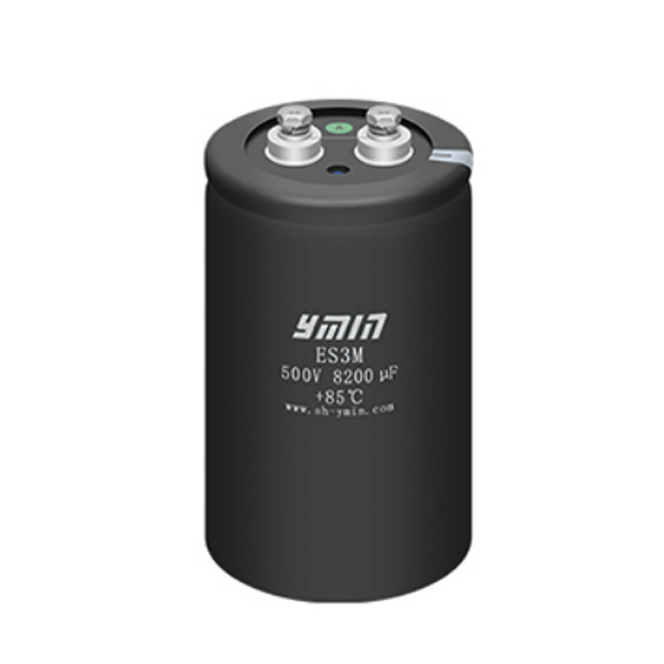
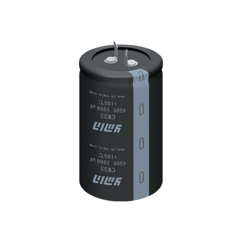
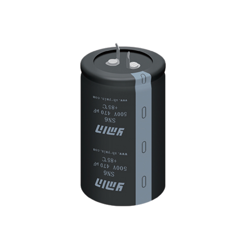
Main technical parameters
| Item |
characteristic |
||||||||
| Operating
temperature range |
-40~+105℃ | ||||||||
| Nominal voltage range | 400-500V | ||||||||
| Capacity tolerance | ±20% (25±2℃ 120Hz) | ||||||||
| Leakage current(uA) | 400-500WV I≤0.015CV+10(uA) C: Nominal capacity (uF) V: Rated voltage (V) 2 minutes reading | ||||||||
| Loss tangent
(25±2℃ 120Hz) |
rated Voltage(V) | 400 | 450 |
500 |
|||||
| tgδ | 0.15 | 0.18 |
0.20 |
||||||
| Temperature
characteristics (120Hz) |
rated Voltage(V) |
400 |
450 | 500 | |||||
| impedance ratio Z(-40℃)/Z(20℃) |
7 |
9 |
9 |
||||||
| Durability | In a 105℃ oven, apply the rated voltage including the rated ripple current for the specified time, then place it at room temperature for 16 hours and then test. The test temperature is 25±2℃. The performance of the capacitor should meet the following requirements. | ||||||||
| Capacity change rate | Within ±20% of initial value | ||||||||
| Loss tangent | Below 200% of the specified value | ||||||||
| Leakage Current | below the specified value | ||||||||
| Load life | ≤Φ 6.3 | 2000 Hrs | |||||||
| ≥Φ8 | 3000Hrs | ||||||||
| High temperature and humidity | After storage for 1000 hours at 105°C, test at room temperature for 16 hours. The test temperature is 25±2°C. The performance of the capacitor should meet the following requirements. | ||||||||
| Capacity change rate | Within ±20% of initial value | ||||||||
| Loss tangent | Below 200% of the specified value | ||||||||
| Leakage Current | Below 200% of the specified value | ||||||||
Product Dimensional Drawing
Dimension (unit:mm)
|
D |
5 |
6.3 |
8 |
10 |
12.5~13 |
14.5 | 16 | 18 |
|
d |
0.5 |
0.5 |
0.6 |
0.6 | 0.7 | 0.8 | 0.8 | 0.8 |
|
F |
2.0 |
2.5 |
3.5 |
5.0 | 5.0 | 7.5 | 7.5 | 7.5 |
|
a |
L<20 a=±1.0 L ≥20 a=±2.0 |
|||||||
Ripple Current Frequency Correction Coefficient
| Frequency(Hz) |
50 |
120 |
1K |
10K-50K |
100K |
|
coefficient |
0.40 |
0.50 |
0.80 |
0.90 |
1.00 |
Aluminum Electrolytic Capacitors: Widely Used Electronic Components
Aluminum electrolytic capacitors are common electronic components in the field of electronics, and they have a wide range of applications in various circuits. As a type of capacitor, aluminum electrolytic capacitors can store and release charge, used for filtering, coupling, and energy storage functions. This article will introduce the working principle, applications, and pros and cons of aluminum electrolytic capacitors.
Working Principle
Aluminum electrolytic capacitors consist of two aluminum foil electrodes and an electrolyte. One aluminum foil is oxidized to become the anode, while the other aluminum foil serves as the cathode, with the electrolyte usually being in liquid or gel form. When a voltage is applied, ions in the electrolyte move between the positive and negative electrodes, forming an electric field, thereby storing charge. This allows aluminum electrolytic capacitors to act as energy storage devices or devices that respond to changing voltages in circuits.
Applications
Aluminum electrolytic capacitors have widespread applications in various electronic devices and circuits. They are commonly found in power systems, amplifiers, filters, DC-DC converters, motor drives, and other circuits. In power systems, aluminum electrolytic capacitors are typically used to smooth output voltage and reduce voltage fluctuations. In amplifiers, they are used for coupling and filtering to improve audio quality. Additionally, aluminum electrolytic capacitors can also be used as phase shifters, step response devices, and more in AC circuits.
Pros and Cons
Aluminum electrolytic capacitors have several advantages, such as relatively high capacitance, low cost, and a wide range of applications. However, they also have some limitations. Firstly, they are polarized devices and must be connected correctly to avoid damage. Secondly, their lifespan is relatively short and they may fail due to electrolyte drying out or leakage. Moreover, the performance of aluminum electrolytic capacitors may be limited in high-frequency applications, so other types of capacitors may need to be considered for specific applications.
Conclusion
In conclusion, aluminum electrolytic capacitors play an important role as common electronic components in the field of electronics. Their simple working principle and wide range of applications make them indispensable components in many electronic devices and circuits. Although aluminum electrolytic capacitors have some limitations, they are still an effective choice for many low-frequency circuits and applications, meeting the needs of most electronic systems.
| Products Number | Operating temperature (℃) | Voltage(V.DC) | Capacitance(uF) | Diameter(mm) | Length(mm) | Leakage current (uA) | Rated ripple current [mA/r.m.s] | ESR/ Impedance [Ωmax] | Life (hrs) | Certification |
| KCMD1202G150MF | -40~105 | 400 | 15 | 8 | 12 | 130 | 281 | - | 3000 | —— |
| KCMD1402G180MF | -40~105 | 400 | 18 | 8 | 14 | 154 | 314 | - | 3000 | —— |
| KCMD1602G220MF | -40~105 | 400 | 22 | 8 | 16 | 186 | 406 | - | 3000 | —— |
| KCMD1802G270MF | -40~105 | 400 | 27 | 8 | 18 | 226 | 355 | - | 3000 | —— |
| KCMD2502G330MF | -40~105 | 400 | 33 | 8 | 25 | 274 | 389 | - | 3000 | —— |
| KCME1602G330MF | -40~105 | 400 | 33 | 10 | 16 | 274 | 475 | - | 3000 | —— |
| KCME1902G390MF | -40~105 | 400 | 39 | 10 | 19 | 322 | 550 | - | 3000 | —— |
| KCML1602G390MF | -40~105 | 400 | 39 | 12.5 | 16 | 322 | 562 | - | 3000 | —— |
| KCMS1702G470MF | -40~105 | 400 | 47 | 13 | 17 | 386 | 668 | - | 3000 | —— |
| KCMS1902G560MF | -40~105 | 400 | 56 | 13 | 19 | 458 | 825 | - | 3000 | —— |
| KCMD3002G390MF | -40~105 | 400 | 39 | 8 | 30 | 244 | 440 | 2.5 | 3000 | - |
| KCMD3002G470MF | -40~105 | 400 | 47 | 8 | 30 | 292 | 440 | 2.5 | 3000 | - |
| KCMD3502G470MF | -40~105 | 400 | 47 | 8 | 35 | 292 | 450 | 2.5 | 3000 | - |
| KCMD3502G560MF | -40~105 | 400 | 56 | 8 | 35 | 346 | 600 | 1.85 | 3000 | - |
| KCMD4002G560MF | -40~105 | 400 | 56 | 8 | 40 | 346 | 500 | 2.5 | 3000 | - |
| KCME3002G680MF | -40~105 | 400 | 68 | 10 | 30 | 418 | 750 | 1.55 | 3000 | - |
| KCMI1602G680MF | -40~105 | 400 | 68 | 16 | 16 | 418 | 600 | 1.58 | 3000 | - |
| KCME3502G820MF | -40~105 | 400 | 82 | 10 | 35 | 502 | 860 | 1.4 | 3000 | - |
| KCMI1802G820MF | -40~105 | 400 | 82 | 16 | 18 | 502 | 950 | 1.4 | 3000 | - |
| KCMI2002G820MF | -40~105 | 400 | 82 | 16 | 20 | 502 | 1000 | 1.4 | 3000 | - |
| KCMJ1602G820MF | -40~105 | 400 | 82 | 18 | 16 | 502 | 970 | 1.4 | 3000 | - |
| KCME4002G101MF | -40~105 | 400 | 100 | 10 | 40 | 610 | 700 | 1.98 | 3000 | - |
| KCML3002G101MF | -40~105 | 400 | 100 | 12.5 | 30 | 610 | 1000 | 1.4 | 3000 | - |
| KCMI2002G101MF | -40~105 | 400 | 100 | 16 | 20 | 610 | 1050 | 1.35 | 3000 | - |
| KCMJ1802G101MF | -40~105 | 400 | 100 | 18 | 18 | 610 | 1080 | 1.35 | 3000 | - |
| KCME5002G121MF | -40~105 | 400 | 120 | 10 | 50 | 730 | 1200 | 1.25 | 3000 | - |
| KCML3502G121MF | -40~105 | 400 | 120 | 12.5 | 35 | 730 | 1150 | 1.25 | 3000 | - |
| KCMS3002G121MF | -40~105 | 400 | 120 | 13 | 30 | 730 | 1250 | 1.25 | 3000 | - |
| KCMI2502G121MF | -40~105 | 400 | 120 | 16 | 25 | 730 | 1200 | 1.2 | 3000 | - |
| KCMJ2002G121MF | -40~105 | 400 | 120 | 18 | 20 | 730 | 1150 | 1.08 | 3000 | - |
| KCMI2502G151MF | -40~105 | 400 | 150 | 16 | 25 | 910 | 1000 | 1 | 3000 | - |
| KCMI3002G151MF | -40~105 | 400 | 150 | 16 | 30 | 910 | 1450 | 1.15 | 3000 | - |
| KCMJ2502G151MF | -40~105 | 400 | 150 | 18 | 25 | 910 | 1450 | 1.15 | 3000 | - |
| KCMJ2502G181MF | -40~105 | 400 | 180 | 18 | 25 | 1090 | 1350 | 0.9 | 3000 | - |
| KCM E4002W680MF | -40~105 | 450 | 68 | 10 | 40 | 469 | 890 | 1.6 | 3000 | - |
| KCMJ1602W680MF | -40~105 | 450 | 68 | 18 | 16 | 469 | 870 | 1.6 | 3000 | - |
| KCMI2002W820MF | -40~105 | 450 | 82 | 16 | 20 | 563.5 | 1000 | 1.45 | 3000 | - |
| KCMJ2002W101MF | -40~105 | 450 | 100 | 18 | 20 | 685 | 1180 | 1.38 | 3000 | - |
| KCMS5002W151MF | -40~105 | 450 | 150 | 13 | 50 | 1022.5 | 1450 | 1.05 | 3000 | - |
